
Digital Electronics and Logic Gates
Digital Electronics and Logic Gates: Overview
The important digital circuits performing special logic operations are called logic gates. In this topic, we will learn the concepts and formulas related to the functioning of digital electronics and logical gates with examples.
Important Questions on Digital Electronics and Logic Gates
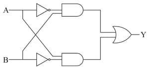
Solve the logical gate and find the truth table.
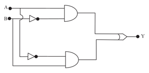
The truth table for the following logic circuit is
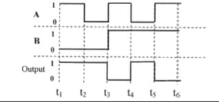
The Input and Output waveform of a GATE are given in the figure below.Identify the gate and write its truth table:
Name the two gates that can be used to form NOT gate.
How can a NOR gate be convereted into a NOT gate?
How many input combinations are possible in a two input NAND gate, when it is working as a NOT gate.
While realising a NOT gate, for low input, n-p-n transistor is in cut-off mode.
How the switches, battery and bulb are connected for the demonstration of working of OR gate?
In the formation of a two-input OR gate using two diodes, negative terminal of one diode is connected to the positive terminal of another diode.
OR gate can be represented by the two switches in series connected with a bulb and battery.
How is a NOT gate realised with the help of a transistor?
How does a NOT gate work in a circuit?
Draw the transistor based circuit diagram for NOT gate and also give its truth table.
How IS NOR gate represented with switches and bulbs?
A self-controllable voltage level (svl) circuit and its low-power high-speed cmos circuit applications;
Digital testing of high voltage circuit breaker of;
Explain how voltage levels are interpreted by a digital circuit ?
What are analog and digital signals? Explain.
A device that converts digital signals to analog signals is _____.
What is the difference between analogue signal and digital signal ?


